
Blog de diseño óptico
Telephoto
Telephoto
Ocular 10x Apocromático.
Objective to inspect....pizzas.
During part of my training, I did a "Master in Photonics" in which there was a subject called "Building Optometrical System", taught by Professor Josep Arasa. I would like to take this opportunity to thank him for all the knowledge he gave us. During the course we solved an optical design problem.
In this entry I present two solutions to the problem. One is going to be very strict (respecting all the requirements specified below) and simple, while the second solution is more complex.
The system is an objective that has to inspect pizzas whose requirements are:
-
The size of the object is 400 mm.
-
The smallest detail to be resolved is 4 mm, less than 5% distortion. The thickness of the pizzas can vary 25 mm. In the worst case, the distortion will not exceed 8% and the image will maintain 80% nominal quality.
-
From the distortion test we will obtain the quality test of the system. The blurred line should be less than 150% of the line thickness, i.e. the line thickness at 50% of the grey level should be less than 1.5 mm when the monochromatic wavelength test was performed.
-
The system works with an f/4 number.
-
The solution must cost 200€.
-
The distance of the object will be between 1000 mm and 1200 mm.
-
The protective glass will have a thickness of 20 mm and manufactured in BK7.
-
The temperature range will be from 5º to 50º.
-
The camera sensor will be model IU-5580RE-C-HQ.
For now we know that we need a system that works with f/4 for a field of 400 mm and that the object is located between 1000-1200 mm with the possibility of varying the thickness 25 mm. The sensor, which is imposed on us, has a size of 5.632 mm x 4.224 mm and a pixel size of 2.2 microns.
From here we can clear that the angular magnification that we are going to need is -0.01 (we suppose that the image will be inverted). It is also important to look at the "C-mount" parameter of the camera. The camera needs the focal image to be formed at least 17.53 mm. It is very important to keep this in mind because we could reach a solution that forms the image at 10 mm from the lens, not being this one valid.
To find the focal point of the system, what we are going to do is use Newton's formulas and we are going to place our object at a distance equal to the distance from the image focal plane to the object. That is, z=1000. And from the object to the lens there is z+efl.

Figure 1. Newton's paraxial formulas.
From this we can deduce that our system will have a focal length of -10 mm. A single lens would be useless because we need the rear distance to be greater than 17.53 mm. What we do is divide the system in two. The lateral increase of the system has to be 0.01 (absolute value), so each part of the system will have a lateral increase of 0.1.
When we do the calculations with the divided system, we will see that the focal point of the system is now -9.52 mm. From here, by means of the paraxial formulation, we find the focal points of the two lenses, the space between them, the position of the main planes, the depth of geometric focus and the diameters of the lenses. In fact, the diameter of the lenses is what forces us to select the second lens as the aperture diaphragm, because if the aperture diaphragm were in the first lens, the diameter would be too large.
In Figure 2 we see the results of the calculated paraxial system. The next step is to introduce this into Zemax and start optimizing the system until the desired quality is achieved.
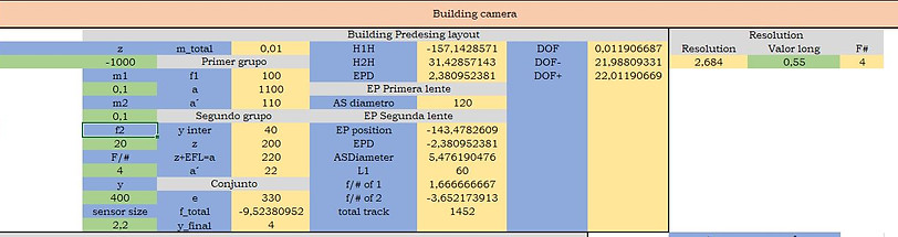
Figure 2. Paraxial calculations of our system.
From Figure 2 we can see that Airy's disk will have a size of 2.684 microns, very similar to the size of the pixel.
Knowing the power of each group, I calculate two achromatic doubles and enter all the data into Zemax. As all the calculations made so far have been paraxial, the system at this point of the process is not good, being necessary to optimize it.
During the optimization process we see that the first group generates many aberrations and made a "power splitting" of the first group, getting to improve the result. Finally, we optimize everything and obtain the required system fulfilling all the conditions.
Figure 3 presents a strict solution. This solution uses only one meniscus and one doublet at the front and one doublet at the rear.
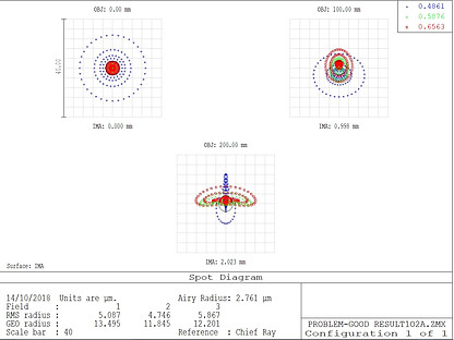


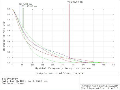


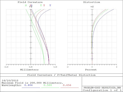

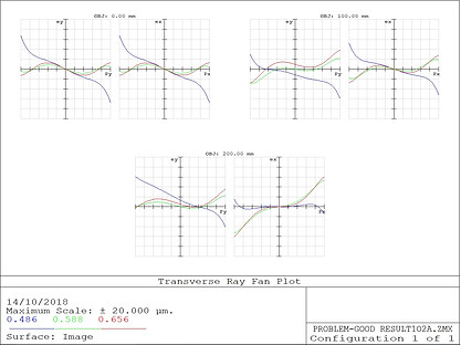

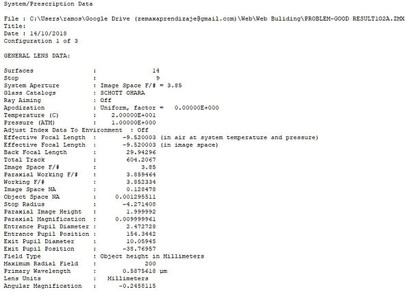
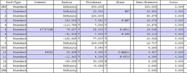
Figure 3. System already optimized and strict.
The system presents a Spot Size RMS of 5.087, 4.76 and 5.876 microns in the fields of 0, 100 and 200 mm. This point size is smaller than required in the specifications. Using a multiconfiguration we verify that if we move the object ±25 mm from the original position, the point size remains practically the same. Another specification achieved.
The system is achromatic as can be seen in the "Chromatic Focal Shift" graph, with a maximum focal displacement range of 23.68 microns. However, the system is achromatic at the pupil position (0.0).
The field curvature is less than 0.1 mm and the distortion less than 2%, when the requirement was less than 5%. The OPD graphics and the Tranverse Ray Fan Plot are good enough, as the scale of the graphics is 2 waves and 20 microns respectively.
In the Lens Data of Figure 4 we can see the selected crystals. They are all from the Schott house. In addition, I want to clarify one thing: in the problem we were urged that the target would have to be between 1000 and 1200 mm pizza. The working distance on this problem I have taken from the object to the first lens, from the object to the protective film. In many books, such as "Perspective on Modern Optics and Imaging" by Ronian Siew, we are warned that it is necessary to establish well what is the working distance, since we could think that the working distance is from the front of "Lens Housing".
To end this article, I show a proposal that does NOT comply with the initial conditions established but that represents an abysmal improvement over the previous system.
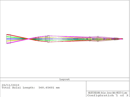
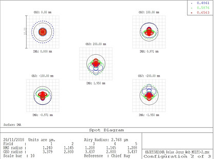
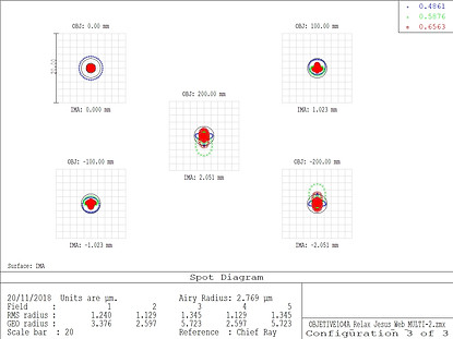
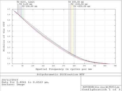
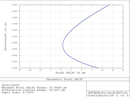
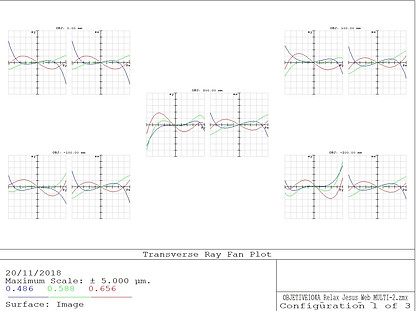
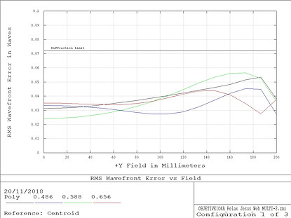

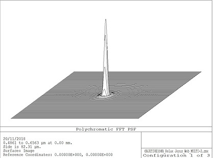
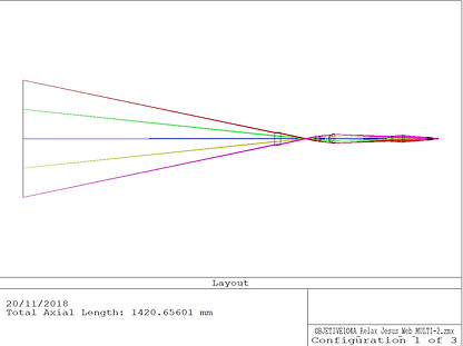
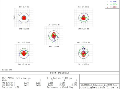

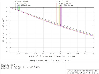
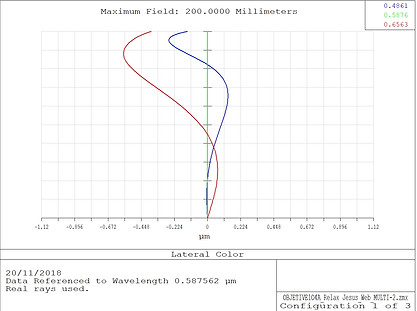


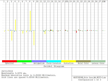
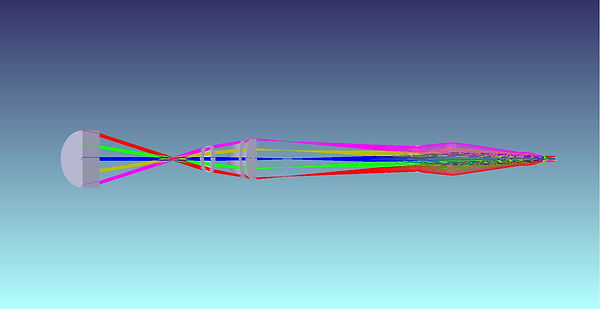

Figure 4. Relaxed System Report.
In this case, the system is limited difracted. To reduce costs, I used the "crystal replacement" tool by setting the condition to use only "Standard" or "Preferred" crystals with a maximum cost of 2.0. Even so, I went a little over the 200€ budget.
The system is formed by four groups of lenses, where I use 5 singlets, 3 doublets and a triplet.
The Spot Size RMS of the system (including the possible ±25 mm blur) is smaller than the radius of the Airy disc. In this case, the lateral color is less than half the size of the pixel, being in the worst case 0.5 microns. Relative illumination is above 90% in all fields.
The OPD graphics and the Tranverse Ray Fan Plot now have a scale of 0.2 waves and 5 microns respectively, which is a tremendous improvement over the previous design.
Now the FFT MTF is very close to the diffraction limit. The FFT PSF graph shows that the system is very well compensated, showing the typical cone of a system limited by diffraction. Although I don't show it here, in the 200 mm field it is the same graph.
The system presents a field curvature less than 0.05 mm and a distortion less than 0.6%, well below what was initially required. The system is still achromatic, but this time it is a pupil position of 0.707.
In order not to make the article longer, I will leave the tolerance analysis for another article.
If you found this article interesting, let me know. Below you can find my contact data.
Thank you very much! See you around!